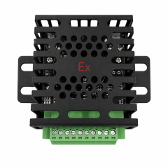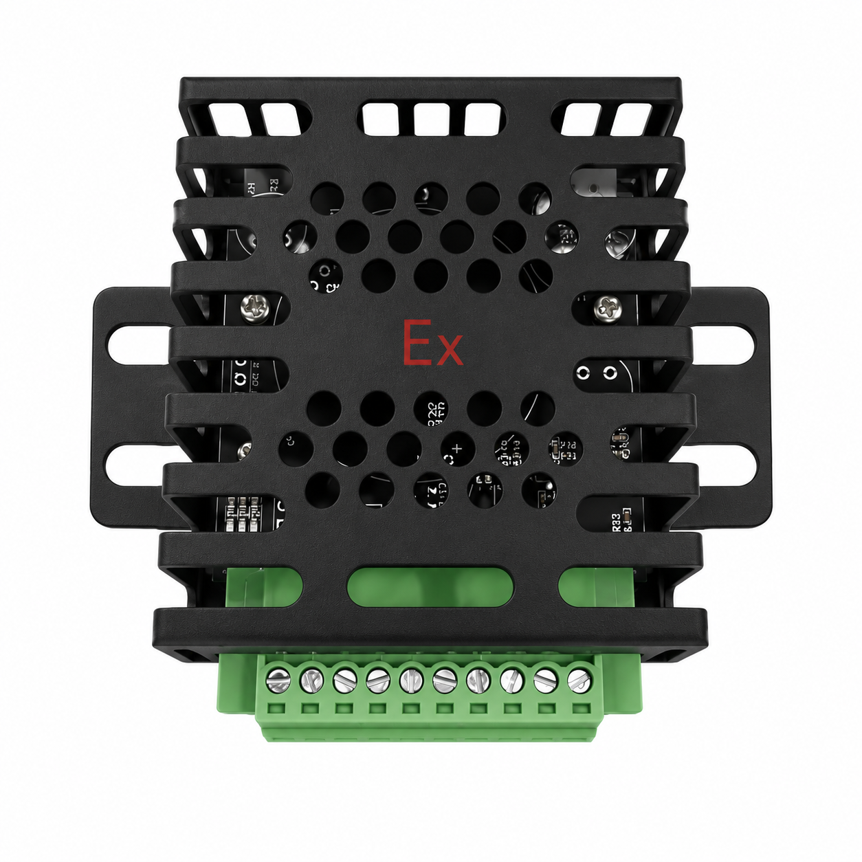
The ANWETECH AT-GD209 is a configurable lithium battery multi-sensor detector combining CO, H₂, VOC, smoke and temperature monitoring with flexible system interfaces including CAN, RS485, dry-contact input and 24 VDC active output.
Designed for installation inside lithium-ion battery enclosures, the detector can transmit monitoring and alarm information to a compatible BMS or controller, while its active 24 VDC output can be used for configured alarm or control actions.
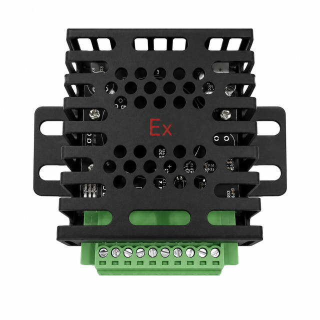
AT-GD209 is designed for lithium-ion battery applications where one detector needs to perform both multi-parameter condition monitoring and external system communication.
Depending on the ordered configuration, the detector can monitor:
The detector uses the available sensor signals to identify abnormal battery conditions and developing fire stages. Depending on the sensor configuration, up to four alarm levels can be implemented.
Unlike a conventional standalone smoke detector, AT-GD209 also provides several external interfaces:
CAN → BMS communication
RS485 → Controller / host communication
Dry Contact Input → Feedback / external input
24 VDC Active Output → Alarm / control signal
This combination makes the detector particularly suitable for lithium battery systems where fire detection needs to be integrated with existing monitoring, control or protection equipment.
AT-GD209 is a configurable detector platform. The final sensor combination must follow the ordered product configuration.
The user manual includes alarm-logic examples for configurations such as:
These combinations are configuration examples and do not mean that every AT-GD209 contains all five sensor types.
For project selection, the sensor combination should be confirmed according to the battery system, required monitoring parameters and system interface requirements.
| Parameter | Specification |
|---|---|
| Model | AT-GD209 |
| Product Type | Lithium Battery Multi-Sensor Detector |
| Supported Sensor Types | CO, H₂, VOC, Smoke, Temperature; configurable |
| Operating Voltage | DC 9–30 V |
| Device Power | < 5 W |
| Operating Temperature | -40°C to +125°C |
| Operating Humidity | < 95% RH |
| Storage Temperature | -40°C to +125°C |
| Atmospheric Pressure | 550–1060 hPa |
| Temperature Range | -40°C to +125°C |
| CO Measurement Range | 0–1000 ppm |
| H₂ Measurement Range | 0–1000 ppm |
| VOC Alarm Levels | Up to 3 levels |
| Smoke Alarm Threshold | 1.0 dB/m, adjustable |
| Protected Space | 1 m³ |
| Communication | CAN / RS485 |
| External Input | Dry-contact feedback/input |
| Active Output | 24 VDC |
| Maximum Active Output Current | 2 A |
| Output Behavior | Continuous while active; removed after reset |
| Alarm Levels | Up to 4 levels, depending on configuration |
| Terminal Block | 3.81 mm pluggable terminal block |
| Technical Marking Stated in Manual | Ex ib IIC T6 Gb |
One of the main characteristics of AT-GD209 is that detection and system integration are combined in the same device.
Terminals 1 and 2 provide the CAN interface:
CAN can be used to connect the detector to a compatible Battery Management System (BMS) for transmission of detector information.
Terminals 5 and 6 are configured as RS485 by default:
RS485 can be used for connection to a compatible controller or monitoring host.
The presence of an RS485 interface does not automatically mean that all third-party devices are directly compatible. The communication protocol must also match.
Terminals 7 and 8 are used as the dry-contact feedback/input pair:
These terminals are input / feedback terminals, not a dry-contact alarm output.
Terminals 9 and 10 provide the active 24 VDC output:
The confirmed output characteristics are:
Active Output Voltage: 24 VDC
Maximum Output Current: 2 A
Output Type: Continuous active output
Reset Behavior: Output is removed after system reset
This interface can be incorporated into a configured alarm or control architecture where an active 24 VDC signal is required.
| No. | Terminal | Function |
|---|---|---|
| 1 | CAN H | CAN communication high |
| 2 | CAN L | CAN communication low |
| 3 | GND | Power supply negative / ground |
| 4 | VIN | DC 9–30 V positive input |
| 5 | RS485 A / 24V− | RS485 A by default; configurable level output when CAN is used |
| 6 | RS485 B / 24V+ | RS485 B by default; configurable level output when CAN is used |
| 7 | Feedback − | Dry-contact feedback/input negative |
| 8 | Feedback + | Dry-contact feedback/input positive |
| 9 | 24V− | Active 24 VDC output negative |
| 10 | 24V+ | Active 24 VDC output positive |
The AT-GD209 does not rely on only one fire parameter.
Depending on configuration, the detector can combine gas, smoke and temperature information to identify different stages of abnormal battery conditions.
For example, the documented five-sensor configuration combines:
Smoke + Temperature + CO + H₂ + VOC
and uses four internal stages:
| Level | Detection Stage |
|---|---|
| Level 1 | Early Thermal Runaway |
| Level 2 | Initial Smoldering |
| Level 3 | Intensified Smoldering |
| Level 4 | Open-Flame Fire |
In this configuration, Level 1 functions as an early thermal-runaway monitoring stage with increased sampling frequency, while the later stages provide external alarm reporting. At the highest stage, the detector can activate the 24 VDC output.
This staged logic allows the detector to use different combinations of gas concentration, smoke and temperature rather than relying on one sensing parameter alone.
A typical battery monitoring architecture is:
AT-GD209 → CAN → BMS
The detector can be installed inside the battery enclosure and periodically transmit detector data through CAN.
Another configuration is:
AT-GD209 → RS485 / CAN → Controller
A compatible controller can receive detector information and perform additional audible/visual alarm or fire-protection control functions according to the project design.
AT-GD209 is not presented in the manual as a conventional addressable fire alarm detector directly connected to every type of fire alarm control panel.
Where integration with a conventional or addressable fire alarm panel is required, the panel input type should first be confirmed.
A suitable:
Interface Relay
or
Addressable Monitor Module
may be required between the AT-GD209 and the fire alarm control panel.
The manual specifies that AT-GD209 is normally installed inside the lithium-ion battery enclosure.
The installation position should allow the configured sensors to monitor the protected air space while keeping the sensing openings unobstructed.
Before wiring:
| Item | Value |
|---|---|
| Overall Width Including Mounting Ears | 89.4 mm |
| Overall Height | 65.0 ± 0.5 mm |
| Enclosure Thickness | 17.9 ± 0.5 mm |
| Main Body Width | 60.3 ± 0.5 mm |
| Terminal Block | 3.81 mm pluggable type |
The compact enclosure is intended for installation inside battery equipment where installation space is limited.
Based strictly on the confirmed user manual, AT-GD209 is suitable for:
The manual defines the stated protected space as 1 m³, so the product should primarily be presented as a battery-enclosure detector, rather than a general room-level ceiling fire detector.